Precision Couplings
One line divides them: whether the coupling can compensate misalignment. Get that straight and most selection errors disappear.
A rigid coupling treats two shafts as one shaft. There is no elastic element, so angular, parallel and axial offsets are all absorbed by the bearings and the shafts themselves. A flexible coupling places a deformable element between the shafts - a metal diaphragm, a TPU elastomer, an engineered plastic slider, or a machined metal beam - which transmits torque while absorbing the offset. The first question in any selection is therefore always the same: will this application have misalignment? If the answer is yes, rigid couplings are ruled out.
Rigid couplings (sleeve and flanged types) are not obsolete. They are correct when three conditions hold at once: the two shafts are aligned to high precision, the shaft spacing will not change with thermal growth, and there is no shock load. Typical cases are pump extension shafts, segmented agitator shafts, and rigid drive trains on test rigs. Their advantages are the simplest possible construction, the lowest cost, and zero torsional deflection. The flip side: if the machine is assembled by hand and aligned with a dial gauge, the residual misalignment is enough for a rigid coupling to destroy the bearings. That failure mode is one of the most common coupling-related bearing failures in the field.
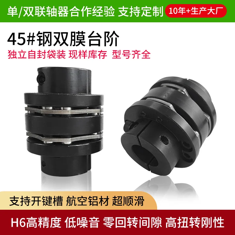
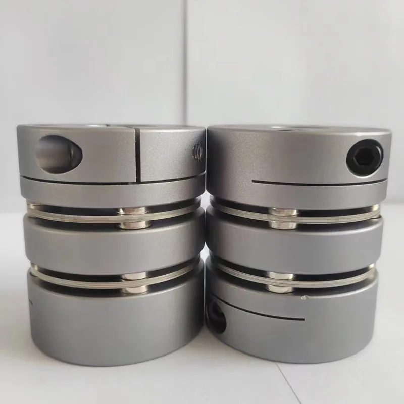
Flexible couplings split into four practical groups by what they compensate with. First, diaphragm couplings use elastic deflection of a stainless steel disc - available in a standard and a heavier version - giving zero backlash, the highest torsional stiffness and no maintenance, and they dominate servo drives on precision ball screws. Second, jaw couplings use a TPU polyurethane spider, in aluminium clamping versions and stainless expansion-sleeve versions, giving vibration damping with a replaceable elastomer, well suited to general industrial drives and to wet or aggressive environments. Third, cross-slider couplings use an engineered plastic slider and offer the largest parallel offset compensation, which suits poorly aligned, moderate-speed applications. Fourth, beam or parallel-line couplings use a machined metal beam, giving zero backlash and very low inertia for encoders and small precision axes.
Misalignment is not one number but three, and a given series compensates each of them independently. Angular misalignment means the two axes meet at an angle, expressed in degrees. Parallel offset means the axes are parallel but not collinear, expressed in millimetres. Axial offset means the gap between shaft ends changes, usually from thermal growth or thrust, expressed as plus or minus millimetres. A diaphragm family typically compensates on the order of 0.1 to 1 degree of angular offset, while the heavier version narrows angular range but extends parallel compensation to around 1.3 mm. A jaw family covers a wider angular band with far less parallel capacity, and a cross-slider design is the reverse. Choosing the wrong axis of compensation is worse than choosing a smaller size: undersizing shortens life, but the wrong type either will not assemble or fails immediately.
Question one: can the two shafts be aligned precisely and stay that way? If yes, and the load is steady, rigid is an option. If no, flexible is mandatory. Question two: do you care more about positioning accuracy or about damping? For accuracy, choose diaphragm or beam. For damping, choose jaw. Question three: what is the environment? Wet, corrosive, washdown or sanitary calls for a stainless series; a dry workshop at room temperature is served by aluminium. Write down those three answers and the remaining work is reading outer diameter and bore size off the catalogue.
Mistake one: assuming a flexible coupling does not need alignment. Compensation is finite, and asking for more than the rated deflection fatigues the flexure early. The fracture surface then looks like a manufacturing defect when it is an application error. Mistake two: saving money by putting a rigid or cross-slider coupling on a precision servo axis. A rigid part has no compensation at all, and a slider design has built-in sliding clearance; both produce a positioning error that no amount of tuning removes. The price of these two mistakes is usually one unplanned stop plus one replacement motor shaft.
One line divides them: whether the coupling can compensate misalignment. Get that straight and most selection errors disappear.
Free Selection Help →| Payment | 50% deposit, balance before shipment |
|---|---|
| Bank transfer | Company-to-company only, no personal accounts |
| Packaging | Carton, or pallet with wooden case by quantity |
| Certification | ISO 9001 |